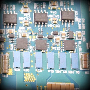
PWM generator circuit
This circuit utilizes a triangle wave generator and comparator to generate a
500 kHz pulse-width modulated (PWM) waveform with a duty cycle that is
inversely proportional to the input voltage. An op amp and comparator
generate a triangle waveform which is applied to the inverting input of a
second comparator. The input voltage is applied to the non-inverting input of
this second comparator. By comparing the input waveform to the triangle wave,
a PWM waveform is produced. The second comparator is placed in the feedback
loop of an error amplifier to improve the accuracy and linearity of the
output waveform.
View our portfolio of operational amplifiers
http://www.ti.com/amplifier-circuit/o...
Learn more about analog signal chain in our online classroom, TI Precision Labs
https://training.ti.com/ti-precision-...
Evaluate and prototype with amplifiers using TI’s DIYAMP-EVM
http://www.ti.com/tool/DIYAMP-EVM?HQS...
Learn more about the circuit from this video
http://www.ti.com/tool/CIRCUIT060010?...


No comments