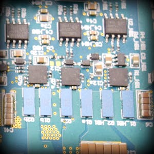
Design Failure Mode and Effects Analysis (DFMEA) for MOSFETs
Design Failure Mode and Effects Analysis (DFMEA) is a structured method for identifying potential failure modes within a product, assessing their effects, and implementing measures to mitigate these risks. In this blog, we will focus on the DFMEA for Metal-Oxide-Semiconductor Field-Effect Transistors (MOSFETs), critical components in electronic circuits. MOSFETs are used for switching and amplifying electronic signals. Despite their robustness, MOSFETs can fail in various ways, impacting circuit performance.
Overview of MOSFETs
MOSFETs are semiconductor devices used to switch or amplify electrical signals in various electronic devices. They are widely used in power supplies, motor controllers, amplifiers, and digital circuits due to their high efficiency and fast switching capabilities.
Functions of MOSFETs
- Switching: Control the flow of current in power electronics.
- Amplification: Increase the strength of weak electronic signals.
- Voltage Regulation: Maintain a constant voltage level in power supply circuits.
- Signal Modulation: Modify signals in communication systems.
- Load Driving: Control power delivery to loads such as motors and LEDs.
Failure Modes of MOSFETs
- Open Circuit: The MOSFET fails to conduct in either direction.
- Short Circuit: The MOSFET conducts in both directions, losing its switching capability.
- Gate Oxide Breakdown: The insulating layer between the gate and the channel fails.
- Thermal Runaway: Excessive heat causes degradation or failure of the MOSFET.
- Parameter Drift: The electrical characteristics of the MOSFET change over time.
- Avalanche Breakdown: The MOSFET fails due to excessive voltage.
DFMEA for MOSFETs
The DFMEA process involves identifying potential failure modes, their causes, and effects, followed by evaluating the severity (S), occurrence (O), and detection (D) of each failure mode. The Risk Priority Number (RPN) is calculated as:
Let's detail this process for a MOSFET in a hypothetical electronic device.
Failure Mode Analysis
Open Circuit
- Cause: Overcurrent, mechanical stress, manufacturing defects.
- Effect: Circuit interruption, device malfunction.
- Severity (S): 9 (High impact as the circuit stops functioning)
- Occurrence (O): 3 (Low occurrence with quality manufacturing)
- Detection (D): 5 (Moderate, detectable through functional testing)
- RPN: 135
Short Circuit
- Cause: Overvoltage, thermal stress, manufacturing defects.
- Effect: Loss of switching capability, potential damage to other components.
- Severity (S): 10 (Severe, can lead to device failure)
- Occurrence (O): 3 (Low, with good design practices)
- Detection (D): 4 (Moderate, detectable through current monitoring)
- RPN: 120
Gate Oxide Breakdown
- Cause: Excessive voltage, manufacturing defects, material degradation.
- Effect: Loss of control over the MOSFET, potential damage to the gate drive circuitry.
- Severity (S): 8 (High impact on performance)
- Occurrence (O): 4 (Moderate, influenced by operating conditions)
- Detection (D): 6 (Moderate, may require precise measurement to detect)
- RPN: 192
Thermal Runaway
- Cause: Excessive current, inadequate cooling.
- Effect: Degradation of materials, potential failure.
- Severity (S): 10 (Severe, leads to device failure)
- Occurrence (O): 3 (Low, with proper thermal management)
- Detection (D): 5 (Moderate, detectable through thermal monitoring)
- RPN: 150
Parameter Drift
- Cause: Aging, thermal stress, material degradation.
- Effect: Circuit performance degradation, inaccurate signal amplification.
- Severity (S): 6 (Moderate impact on performance)
- Occurrence (O): 5 (Occasional, influenced by environmental conditions)
- Detection (D): 7 (Low, may require precise measurement to detect)
- RPN: 210
Avalanche Breakdown
- Cause: Excessive voltage spikes, improper circuit design.
- Effect: Permanent damage to the MOSFET, potential circuit failure.
- Severity (S): 9 (High, can lead to device failure)
- Occurrence (O): 3 (Low, with proper design)
- Detection (D): 5 (Moderate, detectable through voltage monitoring)
- RPN: 135
Mitigation Strategies
To reduce the risks associated with these failure modes, consider the following strategies:
Open Circuit Mitigation:
- Use MOSFETs with higher current ratings.
- Implement robust manufacturing quality control.
- Design for mechanical stress relief.
Short Circuit Mitigation:
- Ensure proper voltage derating.
- Implement over-voltage protection circuits.
- Use MOSFETs with appropriate surge ratings.
Gate Oxide Breakdown Mitigation:
- Use high-quality gate oxide materials.
- Implement robust gate drive circuits to prevent over-voltage.
- Ensure proper ESD (electrostatic discharge) protection.
Thermal Runaway Mitigation:
- Optimize thermal management (e.g., heat sinks, proper ventilation).
- Use MOSFETs with appropriate current ratings.
- Implement current limiting features.
Parameter Drift Mitigation:
- Use high-stability MOSFETs.
- Design circuits to compensate for minor parameter changes.
- Implement environmental protection measures.
Avalanche Breakdown Mitigation:
- Use MOSFETs with high avalanche energy ratings.
- Implement proper circuit design to limit voltage spikes.
- Use snubber circuits to absorb excessive energy.
Conclusion
Performing a DFMEA for MOSFETs helps identify potential failure modes and their impacts on the overall system. By understanding these risks and implementing appropriate mitigation strategies, designers can enhance the reliability and performance of their electronic devices. Regularly reviewing and updating the DFMEA as new data and technologies emerge ensures continued product improvement and robustness.
By following these steps, you can effectively manage the risks associated with MOSFETs in your designs, leading to more reliable and efficient electronic products.


No comments