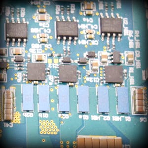
Design Failure Mode and Effects Analysis (DFMEA) for Microcontrollers
Design Failure Mode and Effects Analysis (DFMEA) is a systematic approach to identifying potential failure modes within a product, assessing their effects, and implementing measures to mitigate these risks. In this blog, we will focus on the DFMEA for microcontrollers, which are integral components in embedded systems and play a crucial role in various applications ranging from consumer electronics to industrial automation.
Overview of Microcontrollers
A microcontroller is a compact integrated circuit designed to govern a specific operation in an embedded system. It typically includes a processor, memory, and input/output peripherals on a single chip.
Functions of Microcontrollers
- Processing: Execute instructions and perform computations.
- Memory Management: Store and retrieve data and instructions.
- Input/Output Control: Interface with external devices.
- Communication: Transfer data between the microcontroller and other devices.
- Timing and Control: Generate and manage timing signals.
- Power Management: Manage power consumption and distribution within the system.
Failure Modes of Microcontrollers
- Processor Failure: The microcontroller’s CPU fails to execute instructions correctly.
- Memory Corruption: Data in RAM or flash memory becomes corrupted.
- I/O Port Failure: Input/output ports fail to communicate with external devices.
- Communication Failure: Serial interfaces (e.g., UART, SPI, I2C) fail to transfer data.
- Timing Signal Failure: Timer modules fail to generate accurate timing signals.
- Power Management Failure: The microcontroller fails to manage power properly, leading to excessive power consumption or insufficient power distribution.
- Overheating: Excessive temperature causing malfunction or permanent damage.
- Environmental Susceptibility: Failure due to environmental factors like electromagnetic interference (EMI) or electrostatic discharge (ESD).
DFMEA for Microcontrollers
The DFMEA process involves identifying potential failure modes, their causes, and effects, followed by evaluating the severity (S), occurrence (O), and detection (D) of each failure mode. The Risk Priority Number (RPN) is calculated as:
Let's detail this process for a microcontroller in a hypothetical embedded system.
Failure Mode Analysis
Processor Failure
- Cause: Manufacturing defects, electrical overstress.
- Effect: System crash, loss of functionality.
- Severity (S): 10 (High impact as the system may stop functioning)
- Occurrence (O): 3 (Low occurrence with quality manufacturing)
- Detection (D): 4 (Moderate, detectable through built-in self-test)
- RPN: 120
Memory Corruption
- Cause: Electrical noise, aging, software bugs.
- Effect: Data loss, incorrect operation.
- Severity (S): 9 (High impact on system reliability)
- Occurrence (O): 5 (Occasional, influenced by operating conditions)
- Detection (D): 6 (Low, may require extensive testing to detect)
- RPN: 270
I/O Port Failure
- Cause: Physical damage, ESD, overcurrent.
- Effect: Inability to interface with external devices.
- Severity (S): 8 (High impact on system functionality)
- Occurrence (O): 4 (Moderate, influenced by environmental conditions)
- Detection (D): 5 (Moderate, detectable through functional testing)
- RPN: 160
Communication Failure
- Cause: Faulty interface circuitry, software bugs.
- Effect: Loss of data transfer, communication breakdown.
- Severity (S): 8 (High impact on system functionality)
- Occurrence (O): 4 (Moderate, influenced by operating conditions)
- Detection (D): 5 (Moderate, detectable through communication testing)
- RPN: 160
Timing Signal Failure
- Cause: Oscillator failure, software bugs.
- Effect: Incorrect timing signals, system malfunction.
- Severity (S): 7 (Moderate impact on performance)
- Occurrence (O):: 4 (Moderate, influenced by component quality)
- Detection (D): 6 (Low, may require precise measurement to detect)
- RPN: 168
Power Management Failure
- Cause: Faulty power regulation, thermal issues.
- Effect: Excessive power consumption, insufficient power supply.
- Severity (S): 9 (High impact on system reliability)
- Occurrence (O): 3 (Low, with proper design)
- Detection (D): 5 (Moderate, detectable through power monitoring)
- RPN: 135
Overheating
- Cause: Excessive current, inadequate cooling.
- Effect: Degradation of materials, potential failure.
- Severity (S): 9 (High impact on system reliability)
- Occurrence (O): 3 (Low, with proper thermal management)
- Detection (D): 5 (Moderate, detectable through thermal monitoring)
- RPN: 135
Environmental Susceptibility
- Cause: EMI, ESD.
- Effect: Random failures, data corruption.
- Severity (S): 8 (High impact on system reliability)
- Occurrence (O): 4 (Moderate, influenced by environmental factors)
- Detection (D): 6 (Low, may require environmental testing)
- RPN: 192
Mitigation Strategies
To reduce the risks associated with these failure modes, consider the following strategies:
Processor Failure Mitigation:
- Use robust manufacturing processes.
- Implement thorough built-in self-tests.
- Design for electrical overstress protection.
Memory Corruption Mitigation:
- Use error-correcting codes (ECC) in memory.
- Implement software checks and redundancy.
- Shield against electrical noise.
I/O Port Failure Mitigation:
- Design for ESD protection.
- Implement overcurrent protection.
- Use robust connectors and physical designs.
Communication Failure Mitigation:
- Implement robust interface design.
- Use error-checking protocols.
- Regularly test communication interfaces.
Timing Signal Failure Mitigation:
- Use high-quality oscillators.
- Implement redundant timing sources.
- Regularly test timing accuracy.
Power Management Failure Mitigation:
- Design for proper power regulation.
- Implement thermal management strategies.
- Regularly monitor power consumption.
Overheating Mitigation:
- Optimize thermal management (e.g., heat sinks, proper ventilation).
- Use microcontrollers with appropriate current ratings.
- Implement thermal protection features.
Environmental Susceptibility Mitigation:
- Use shielding and filtering.
- Design for ESD protection.
- Regularly test under various environmental conditions.
Conclusion
Performing a DFMEA for microcontrollers helps identify potential failure modes and their impacts on the overall system. By understanding these risks and implementing appropriate mitigation strategies, designers can enhance the reliability and performance of their embedded systems. Regularly reviewing and updating the DFMEA as new data and technologies emerge ensures continued product improvement and robustness.
By following these steps, you can effectively manage the risks associated with microcontrollers in your designs, leading to more reliable and efficient electronic products.

.png)
.png)


No comments