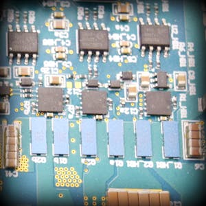
Design Failure Mode and Effects Analysis (DFMEA) for Capacitors
Design Failure Mode and Effects Analysis (DFMEA) is a structured approach to identify potential failure modes within a product, assess their effects, and implement measures to mitigate these risks. In this blog, we will focus on the DFMEA for capacitors, essential components in electronic circuits. Capacitors store and release electrical energy, filter signals, and manage power supply fluctuations. Despite their reliability, capacitors can fail in various ways, impacting the circuit’s performance.
Overview of Capacitors
Capacitors are passive electrical components that store and release electrical energy. They are used in a variety of applications, including filtering, decoupling, timing, and energy storage.
Functions of Capacitors
- Energy Storage: Store and release electrical energy in power supply circuits.
- Filtering: Remove noise from signals in power supplies and audio circuits.
- Decoupling: Isolate different parts of a circuit to prevent interference.
- Timing: Work with resistors to create time delays in oscillator circuits.
- Coupling: Pass AC signals between stages of amplifiers while blocking DC.
Failure Modes of Capacitors
- Open Circuit: The capacitor fails to conduct electricity, breaking the circuit.
- Short Circuit: The capacitor fails, creating a low resistance path.
- Capacitance Drift: The capacitance value changes over time due to aging or environmental factors.
- ESR (Equivalent Series Resistance) Increase: The internal resistance increases, affecting performance.
- Dielectric Breakdown: The insulating material inside the capacitor fails, leading to a short circuit.
- Leakage Current: The capacitor leaks current, reducing its efficiency.
- Mechanical Damage: Physical damage to the capacitor from external forces, such as vibration or impact.
DFMEA for Capacitors
The DFMEA process involves identifying potential failure modes, their causes, and effects, followed by evaluating the severity (S), occurrence (O), and detection (D) of each failure mode. The Risk Priority Number (RPN) is calculated as:
Let's detail this process for a capacitor in a hypothetical electronic device.
Failure Mode Analysis
Open Circuit
- Cause: Overheating, manufacturing defects, mechanical stress.
- Effect: Circuit interruption, device malfunction.
- Severity (S): 9 (High impact as the circuit stops functioning)
- Occurrence (O): 4 (Moderate occurrence with quality manufacturing)
- Detection (D): 5 (Moderate, detectable through functional testing)
- RPN: 180
Short Circuit
- Cause: Dielectric breakdown, contamination, physical damage.
- Effect: Overcurrent, potential damage to other components.
- Severity (S): 10 (Severe, can lead to device failure)
- Occurrence (O): 3 (Low occurrence with good design practices)
- Detection (D): 4 (Moderate, detectable through current monitoring)
- RPN: 120
Capacitance Drift
- Cause: Aging, temperature changes, material degradation.
- Effect: Circuit performance degradation, inaccurate signal filtering.
- Severity (S): 6 (Moderate impact on performance)
- Occurrence (O): 5 (Occasional, influenced by environmental conditions)
- Detection (D): 7 (Low, may require precise measurement to detect)
- RPN: 210
ESR Increase
- Cause: Aging, high ripple currents, poor quality materials.
- Effect: Reduced filtering effectiveness, increased heat generation.
- Severity (S): 7 (High impact on performance)
- Occurrence (O): 4 (Moderate, influenced by operating conditions)
- Detection (D): 6 (Moderate, detectable through impedance testing)
- RPN: 168
Dielectric Breakdown
- Cause: Overvoltage, aging, contamination.
- Effect: Short circuit, potential damage to other components.
- Severity (S): 10 (Severe, leads to device failure)
- Occurrence (O): 2 (Low, with appropriate voltage derating)
- Detection (D): 5 (Moderate, detectable through insulation testing)
- RPN: 100
Leakage Current
- Cause: Dielectric degradation, manufacturing defects.
- Effect: Reduced efficiency, increased power consumption.
- Severity (S): 5 (Moderate impact on efficiency)
- Occurrence (O): 4 (Moderate, influenced by material quality)
- Detection (D): 7 (Low, detectable through leakage current testing)
- RPN: 140
Mechanical Damage
- Cause: External shock, vibration, handling damage.
- Effect: Open circuit, intermittent connections.
- Severity (S): 7 (High, causes circuit instability)
- Occurrence (O): 3 (Low, depends on application environment)
- Detection (D): 6 (Moderate, visual inspection or functional test needed)
- RPN: 126
Mitigation Strategies
To reduce the risks associated with these failure modes, consider the following strategies:
Open Circuit Mitigation:
- Use capacitors with higher voltage ratings.
- Implement robust manufacturing quality control.
- Design for mechanical stress relief.
Short Circuit Mitigation:
- Ensure clean manufacturing processes to prevent contamination.
- Design with adequate clearance and insulation.
- Use capacitors with appropriate dielectric materials and ratings.
Capacitance Drift Mitigation:
- Use high-stability capacitors (e.g., ceramic or film capacitors).
- Design circuits to compensate for minor capacitance changes.
ESR Increase Mitigation:
- Select capacitors with low ESR ratings.
- Ensure proper thermal management to reduce heat-induced degradation.
Dielectric Breakdown Mitigation:
- Use capacitors with higher voltage ratings.
- Implement proper voltage derating in the design.
Leakage Current Mitigation:
- Use high-quality capacitors with low leakage specifications.
- Perform thorough testing during manufacturing.
Mechanical Damage Mitigation:
- Use vibration-resistant mounting techniques.
- Implement protective casing or conformal coating.
Conclusion
Performing a DFMEA for capacitors helps identify potential failure modes and their impacts on the overall system. By understanding these risks and implementing appropriate mitigation strategies, designers can enhance the reliability and performance of their electronic devices. Regularly reviewing and updating the DFMEA as new data and technologies emerge ensures continued product improvement and robustness.
By following these steps, you can effectively manage the risks associated with capacitors in your designs, leading to more reliable and efficient electronic products.


No comments