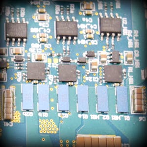
Differential Mode & Common Mode Noise in Input Filter Design
Noise is an unavoidable aspect of electrical systems, particularly in input filters of power supplies, where it can severely impact performance. Two main types of noise are commonly discussed: differential mode noise and common mode noise. Understanding their origins, characteristics, and mitigation techniques is essential for designing effective filters.
What is Differential Mode Noise?
Differential mode noise occurs due to voltage differences between the two conductors in a circuit, typically the live and neutral lines. This type of noise is caused by switching actions within the power supply or other components, which create high-frequency voltage variations.
Main Reasons for Generation:
- Switching Components: Rapid switching in power supplies generates sharp voltage changes.
- Load Variations: Sudden changes in the load can introduce differential noise.
- Impedance Mismatches: Differing impedances in the circuit can lead to voltage differences.
What is Common Mode Noise?
Common mode noise is generated when the same noise signal appears simultaneously on both conductors relative to a common reference point, usually ground. This noise can be introduced by external electromagnetic interference (EMI) or parasitic capacitances within the circuit.
Main Reasons for Generation:
- Electromagnetic Interference (EMI): External sources such as radio frequencies and electromagnetic fields.
- Parasitic Capacitances: Unintentional capacitive coupling between the circuit and other conductive elements.
- Ground Loops: Differences in ground potential can introduce common mode currents.
Differences Between Differential Mode and Common Mode Noise
- Nature:
- Differential Mode: Voltage difference between two conductors.
- Common Mode: Simultaneous voltage on both conductors relative to ground.
- Sources:
- Differential Mode: Internal circuit activities like switching.
- Common Mode: External EMI and ground loops.
- Mitigation Techniques:
- Differential Mode: Differential filtering components such as capacitors and inductors.
- Common Mode: Common mode chokes and shielding.
Best Practices to Eliminate Noise
1. Proper Grounding:
- Ensure a single point grounding to avoid ground loops.
- Use a low impedance ground connection.
2. Shielding:
- Shield cables and enclosures to protect against EMI.
- Use twisted pair cables to minimize inductive coupling.
3. Component Placement:
- Place noisy components away from sensitive circuits.
- Use PCB layout techniques to minimize noise coupling.
4. Filter Design:
- Use differential mode capacitors and inductors to filter differential noise.
- Employ common mode chokes to block common mode noise.
Filter Designs from Low Cost to High Efficiency
Basic RC Filter (Low Cost):
- Components: Resistor (R) and Capacitor (C).
- Usage: Simple circuits with minimal noise issues.
- Advantage: Low cost and easy implementation.
- Disadvantage: Limited filtering capability, not suitable for high-frequency noise.
LC Filter (Moderate Cost):
- Components: Inductor (L) and Capacitor (C).
- Usage: Power supplies and circuits with moderate noise levels.
- Advantage: Better filtering than RC filters, effective for a broader frequency range.
- Disadvantage: More expensive than RC filters and bulkier.
Common Mode Choke (High Efficiency):
- Components: Common mode choke combined with capacitors.
- Usage: Circuits exposed to significant EMI and common mode noise.
- Advantage: Highly effective at blocking common mode noise.
- Disadvantage: Higher cost and complexity.
Pi Filter (High Efficiency):
- Components: Two capacitors and one inductor.
- Usage: High-performance applications requiring stringent noise control.
- Advantage: Excellent filtering performance.
- Disadvantage: Increased cost and complexity.
Additional Techniques to Mitigate Noise
Ferrite Beads:
- Used to suppress high-frequency noise.
- Cost-effective and easy to implement.
Isolation Transformers:
- Provide galvanic isolation to block common mode noise.
- Effective but costly and bulky.
EMI Filters:
- Specialized filters designed to attenuate EMI.
- Can be integrated into power supply units.
Conclusion
Effective noise management in input filter design is crucial for maintaining the integrity and performance of electrical systems. By understanding the sources and characteristics of differential and common mode noise, and employing appropriate filtering techniques from simple RC filters to advanced common mode chokes, designers can significantly reduce noise impact. Balancing cost and efficiency is key, with solutions ranging from low-cost basic filters to high-efficiency, high-performance options. Proper grounding, shielding, and thoughtful component placement further enhance noise mitigation efforts, ensuring robust and reliable circuit operation.
 Reviewed by eeupdate
on
6/14/2024
Rating: 5


.jpg)

No comments