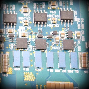
Designing an LC Filter for Noise and Transients in a Circuit
When designing electronic circuits, managing noise and transients is crucial to ensure reliable and stable operation. An effective way to tackle these issues is through the use of LC (inductor-capacitor) filters. These filters can smooth out unwanted noise and transient signals, providing cleaner and more stable output. This blog will guide you through the process of designing an LC filter, including the selection of inductors and capacitors.
1. Understanding LC Filters
An LC filter consists of an inductor (L) and a capacitor (C) arranged in specific configurations to filter out unwanted frequencies. The basic types of LC filters are:
- Low-pass filter (LPF): Passes signals with a frequency lower than a certain cutoff frequency and attenuates higher frequencies.
- High-pass filter (HPF): Passes signals with a frequency higher than a certain cutoff frequency and attenuates lower frequencies.
- Band-pass filter (BPF): Passes signals within a certain range of frequencies and attenuates signals outside this range.
- Band-stop filter (BSF): Attenuates signals within a certain range of frequencies and passes signals outside this range.
2. Basics of Inductors and Capacitors
Inductors: Inductors resist changes in current, creating a magnetic field in response to current flow. The inductance (L) is measured in henrys (H) and determines how effectively the inductor can oppose changes in current.
Capacitors: Capacitors store energy in an electric field and resist changes in voltage. The capacitance (C) is measured in farads (F) and determines how effectively the capacitor can oppose changes in voltage.
3. Design Steps for an LC Filter
Step 1: Define Requirements
- Cutoff Frequency (fc): Determine the frequency at which the filter needs to start attenuating signals. This is based on the specific application requirements.
- Load Impedance (Z): The impedance of the load connected to the filter impacts the design.
- Attenuation: Define how much attenuation is needed beyond the cutoff frequency.
Step 2: Select Filter Type
Choose the type of LC filter based on the application:
- Low-pass: For applications where low-frequency signals need to be passed.
- High-pass: For applications where high-frequency signals need to be passed.
- Band-pass: For applications where a specific range of frequencies needs to be passed.
- Band-stop: For applications where a specific range of frequencies needs to be attenuated.
Step 3: Calculate Component Values
The component values for a simple LC low-pass filter can be calculated using the cutoff frequency formula:
Rearrange this formula to solve for L and C:
For a high-pass filter, the formulas are similar:
Step 4: Selection of Inductor and Capacitor
Inductor Selection:
- Inductance Value (L): Use the calculated value from the above formula.
- Current Rating: Ensure the inductor can handle the maximum current in the circuit without saturating.
- DC Resistance (DCR): Lower DCR values are preferred to minimize power loss.
- Quality Factor (Q): Higher Q indicates lower losses.
Capacitor Selection:
- Capacitance Value (C): Use the calculated value from the above formula.
- Voltage Rating: Ensure the capacitor can handle the maximum voltage in the circuit.
- Equivalent Series Resistance (ESR): Lower ESR values are preferred to minimize power loss.
- Type: Ceramic capacitors are often used for high-frequency applications, while electrolytic capacitors are used for low-frequency applications.
Step 5: Simulation and Testing
- Simulation: Use circuit simulation software (like SPICE) to model the filter and validate its performance against the design requirements.
- Prototyping: Build a physical prototype of the filter and test it in the actual circuit to ensure it meets the desired performance.
4. Practical Considerations
- Parasitics: Real inductors and capacitors have parasitic elements (resistance, inductance, and capacitance) that can affect performance. These should be considered in the design and simulation.
- Thermal Management: Ensure components can handle the thermal load without degradation.
- Component Tolerances: Account for component tolerances and their impact on the filter performance.
- EMI/EMC Compliance: Ensure the filter design meets electromagnetic interference (EMI) and electromagnetic compatibility (EMC) standards.
5. Example Calculation
Let's design a low-pass LC filter with a cutoff frequency of 10 kHz and a load impedance of 50 ohms.
Using the formula for cutoff frequency:
Assuming we choose a capacitor value of 0.1 μF (0.1 x 10^-6 F):
Select an inductor with an inductance close to 253.3 μH, a current rating above the maximum circuit current, and a low DCR.
Conclusion
Designing an LC filter involves understanding the fundamental principles of inductors and capacitors, defining the filter requirements, calculating component values, selecting appropriate components, and validating the design through simulation and testing. By following these steps, you can effectively design LC filters to manage noise and transients in your electronic circuits, ensuring optimal performance and reliability.


No comments