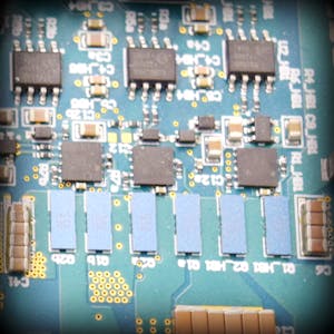
The Critical Role of Test Points in Schematic and Layout Design
In the intricate process of designing electronic circuits, the placement and utilization of test points are often overlooked. Yet, these small, seemingly insignificant points can be the difference between a successful product and one plagued with debugging nightmares. This blog explores the importance of test points in both schematics and layouts, including considerations for the number of test points, optimal locations, and their varying significance.
Why Are Test Points Important?
Test points serve as accessible locations within a circuit where measurements can be taken. They play a vital role in the development, testing, and maintenance phases of a project by providing clear access to critical nodes without disturbing the circuit’s functionality. Here’s why they matter:
- Debugging and Troubleshooting: Test points allow engineers to monitor and diagnose issues during the prototyping and debugging stages.
- Manufacturing Testing: Automated Test Equipment (ATE) utilizes test points to verify the functionality of circuits during manufacturing.
- Field Service and Maintenance: Test points enable service personnel to check the health of circuits in the field without dismantling the device.
Determining the Number of Test Points
The number of test points required depends on the complexity of the circuit and the criticality of certain signals. Here are some guidelines:
- Simple Circuits: For straightforward circuits, a few well-placed test points might suffice. Key areas include power rails, ground, and critical signal paths.
- Complex Circuits: More intricate designs, such as those involving microcontrollers or high-speed digital circuits, necessitate additional test points. Each major functional block should have accessible test points.
- Redundancy: Include redundant test points for critical signals to ensure multiple measurement points in case one becomes inaccessible.
Best Locations for Test Points
Placing test points strategically is crucial for effective testing and debugging. Here are some considerations for optimal placement:
- Power and Ground: Ensure easy access to all power rails and ground planes. These are the most frequently measured points in any circuit.
- Critical Signal Paths: Identify key signals that are vital for the circuit’s operation. Place test points at input and output nodes of important components like microcontrollers, op-amps, and communication interfaces.
- High-Speed Signals: For high-speed circuits, place test points near the source and termination points. Ensure minimal disruption to the signal integrity.
- Isolation Areas: In isolated designs, place test points on both sides of the isolation barrier to verify proper operation and isolation integrity.
- User Interfaces: Include test points at user interface connections (e.g., buttons, LEDs, displays) to verify proper operation.
Varying Importance of Test Points
Not all test points are created equal. Their importance varies based on their role within the circuit:
- Essential Test Points: These are crucial for the primary operation of the circuit, such as main power rails and central signal paths.
- Secondary Test Points: Important for secondary functions and non-critical operations, like auxiliary power supplies or non-essential communication lines.
- Optional Test Points: Used for additional diagnostics and optional features. These can be included for more comprehensive testing but are not strictly necessary for basic operation.
Conclusion
Incorporating test points in your schematic and layout is a best practice that pays off significantly during debugging, testing, and maintenance. By carefully considering the number, location, and importance of test points, you can ensure that your design is robust, testable, and maintainable. A well-thought-out test point strategy can save time, reduce costs, and improve the reliability of your electronic designs.

.png)
.png)


No comments